Reverse Engineering The Seymour Duncan Triple Shot
Seymour Duncan offer a (horrifically overpriced and cheaply made) product particularly attractive to guitar wiring nerds like me - the Triple Shot Mounting Rings.
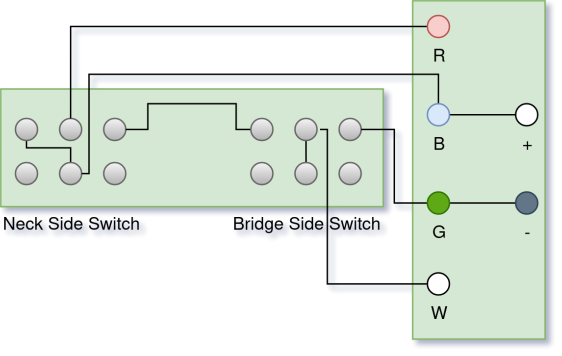
These are humbucker frames that come with a pair of built-in DPDT switches to allow for extensive guitar switching options. Unfortunately, as far as I can tell, nobody on the internet has documented how they’re actually wired.
Naturally, I decided to order myself a pair and figure out all the connections with a multimeter.
A word of explanation: the pickup rings have two PCBs each - one mounted directly beneath the switches inside the ring, and one connected by a ribbon cable that’s meant for the user to solder their pickup leads to.

I’ve drawn the built-in PCB as if you were looking down at the pickup ring flipped face-down, with the PCB at the top; the second PCB is drawn somewhat arbitrarily, but I’ve labeled all the pads.
The switches connect the middle contacts in each row to the contact closer to the switch in that row - ie. if I have the bridge-side switch in the position closer to the neck (left, with the pickup ring face-down), the top middle contact in the neck-side bank will be connected to the top left contact, and the bottom middle contact will be connected to the bottom left contact.
Let’s run through a configuration as an example to make sure we’re on the same page.
Let’s call the contacts in the neck-side bank N1, N2, N3 (top row, neck-side to bridge-side) and N4, N5, N6 (bottom row, neck-side to bridge-side), with N2 and N5 being the commons of the switch.
Similarly, let’s call the contacts in the bridge-side bank B1, B2, B3 (top row, neck-side to bridge-side) and B4, B5, B6 (bottom row, neck-side to bridge-side), with B2 and B5 being the commons of the switch.
If both switches are set to the position closer to the bridge, then:
the R pad is connected to nothing (it connects to N2; the switch connects N2 to N3; the PCB connects N3 to B1, which connects to nothing)
the B pad is connected to + only (it connects to N5; the switch connects N5 to N6, which connects to nothing; the PCB connects N5 to N1, which connects to nothing; B is always connected to +)
the G pad is connected to W and - (it connects to B3; the switch connects B3 to B2; the cable connects B2 to W; the PCB connects B2 to B5; the switch connects B5 to B6, which connects to nothing)
the W pad is connected to G and -, for the same reasons as outlined above.
I hope this is helpful to someone.